LS Models
|
|
Lehmann Porter conversion Info |
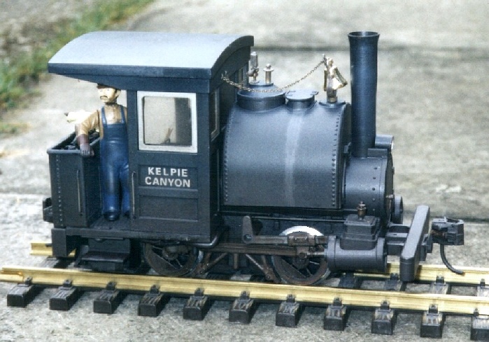 |
Conversion of Lehmann Porter to battery power with radio control and soundNovember 2003 PreambleFirst this is not strictly a Porter. Originally it was a standard Lehmann product with the balloon stack, but some years before battery power was envisaged I modified it to the style seen here. The main changes were shortening the back of the boiler, adding a rear coal bunker and butchering the rear of the cab. When I decided to go with battery power and radio control I was faced with the usual difficulty of a small loco - space (absence thereof). A trailing car is usually prescribed for these engines, but I wanted to operate my railroad, rather than just watch the trains go round, and as this loco was intended to be the 'yard goat' and do a lot of switching work, the use of a trailing van would be irksome to say the least. Adding a tender would mean dispensing with the bunker, which was equally unacceptable. So I did some measuring up of the spaces available. Having already fitted my U30-B with battery + r/c and sound I knew the sizes of the various parts required. I worked out that it should be possible to fit 12 AA batteries, the RCS r/c controller board and a Dallee sound card into the boiler/water tank and bunker, with the RCS r/c receiver card mounted either in the cab or under the footplate. This was definitely not going to be an easy job and I toyed with selling the engine and getting something a little larger. But as much to prove it could be done as for my own use I decided to try for it. The jobTo maximise space the lead ballasts in the tank and boiler were removed and the top of the boiler under the tank cut away. The four screw mount bosses in the tank were also removed and alternative arrangements made to secure it to the boiler. Ten of the batteries were then disposed around the inside of the tank as seen in picture A, but one had to be inset - there was not quite enough space for them to all lie in a neat semicircle on the tank wall. An eleventh was arranged inside the boiler, set slightly rearwards (see pic B), and I gave up on getting 12 in! This battery layout was necessary to allow the r/c controller board to stand vertically inside the boiler and batteries, which is the only space on the loco that it would fit. The batteries are mounted nearer the rear of the tank and the r/c connectors fill some of the space between the batteries and front of the tank (pic B). (Tip. When looking at makers' info on circuit card sizes width and breadth are usually nice square shapes, but the height profile often resembles a city skyline.) The batteries were super-glued together while resting in the inverted tank (making sure the connections were all + to -) and then removed as a pack for soldering up the connections. A fuse and a master switch were fitted in the rear of the shortened boiler. The receiver card was glued under the footplate as I thought this would be most remote from electric interference, but with hindsight I think the front wall of the cab above the boiler would have been better (I had removed the interior steam dome while shortening the boiler). The aerial was extended up and over the cab roof and down the other side before diving into the motor block to connect with one skate. (The other skate and wheel pickups were removed to reduce drag - I did not attempt dual power on this engine.) Sound systemThe soundcard was a straight fit in the bunker as seen in pic A - it's hard to believe I didn't build that bunker to fit the card! (For an unconverted Porter this card could fit down one side of the cab with a cover to hide it.) Two large transistors have their heatsinks poking out the front of the bunker, but painted up they hardly show and if seen look like a couple of steps anyway. The loudspeaker is actually two of the standard 2" units supplied by Dallee wired in series. They are fitted in a false cab roof made from 2 mm black plastic with holes drilled where the speakers are. I wanted a decent chuff sync and found that the opto-sensor from Dallee is thin enough to fit behind the bottom cover of the motor block. I cut a hole in the lip of the block which the sensor can poke through to detect black/white segments on the back of one of the front wheels. (It works better if the sensor is actually at an angle to the wheel.) WiringI wanted to ensure that the major components of the engine could still be separated for servicing so there are a number of connectors used, which do take up space. The main parts are the boiler/tank, the cab and the chassis. The bunker is considered fixed. A 9-pin D connector with the metal shell removed is used for most of the boiler to chassis connections. There is 'waste' space in the motor block above the motor and so the top cover was cut open to make room for this. A 3-pin connector at the front of the motor block is used to get the r/c controller to receiver connection into the boiler, the wires running down the inside of the motor block. Three small 2-pin connectors were used to connect the aerial and loudspeaker connections from the chassis onto the cab (one each side of the cab for the aerial). Another one was used to go from the boiler to a voltage indicator in the cab. A sound and r/c on-off switch is fitted pointing down through one side of the footplate and a charge socket on the other side. The top parts of these and the three connectors above are concealed by plastic 'sand boxes' inside the front of the cab. (This stuff is mostly black and doesn't show up on my pictures - sorry.) The hardest part was wiring to the motor. This involved fitting two 0.1muF suppressor capacitors to the motor terminals in the space on each side of the worm gear. My previous boiler shortening had dropped the top of the cover here by about 5 mm and also forced me to take most of the wiring from the 9-pin connector through this space too. It is very congested. Oh yes, the r/c controller also operates directional lights and bell and whistle, so those have wiring too. A lot of the wiring is run under the footplate and to fix it I just use a drop of superglue every so often - works a treat, but a bit difficult if you decide to change something. There was not space in the bunker for the plug connectors on the sound card, so I soldered the wiring direct to the connector pins on the card. I set up and thoroughly tested the system with the card dangling on the connectors before doing this, since returning the card under warranty afterwards might be tricky! I also removed the volume pot, fitted extension wires, and glued it under the footplate so it can be adjusted. (The sound card is now sealed in the bunker - no access without a knife.) RefinementsWhen all put together it did actually work, but radio control range when not on metal track (which acts as an extension to the aerial via the skate) was very poor at low speeds (about 2 feet) due to the motor/PWM interfering or masking the radio signal. With the help of Tony Walsham at RCS I made a number of mods that improved this considerably, to around 8 feet. Still sounds dreadful but this is OFF the track and was conveniently poor for trying out different suppression solutions in the comfort of the spare room. ON track the range is several times that, and as I don't plan normally to be more than a few feet away I have no problem with the range. I should stress that the coding on the r/c system does not allow the interference to make the loco do strange things, it just blocks the signal getting through the receiver and prevents (e.g.) the loco speed being changed. To improve the resistance to interference I cased the receiver in thin steel sheet and screened the aerial sections from the receiver to the cab connector and between the other side of the cab and the skate. These are the aerial sections that run near the motor wiring. The cable screen and receiver case are connected to battery -ve. The section of antenna that runs up one side of the cab, over the roof and down the other side is not screened, it is supposed to pick up the r/c signal. Ideally I should also use a twin screened cable for the power feeds from the battery to the r/c controller and the sound unit, and also from the r/c controller to the motor, but this would be very difficult to do at this stage. If I'd known at the time of installation it would not have been too hard to do. PerformanceThe reduction to 11 cells actually turned out well. NiMH cell packs of this number should not be discharged below about 1.1 volts per cell, which is about 12 volts for 11 cells, and the electronics are not rated below 12 volts and start to do odd things below that anyway. Good all round. I ran some trials using a mixture of actual running, discharging through a resistor and measuring the typical running current. Running at moderate speed pulling a few cars, with the sound and headlight on, the current drain is about 250...300 mA. The batteries have 1300 mAh capacity so a continuous operating time of about four hours is probable from a full charge. In normal operation, where it will be standing with just the sound sizzling for significant periods, I expect that sessions of six hours or more will be achievable. This is probably more than the big U30-B diesel would achieve and longer than I would usually last anyway, so I was well pleased with this conversion. It was fun to just lift this hissing, chuffing little critter off the track at the club sometimes, and watch peoples faces when it didn't stop hissing and chuffing. Following my departure from Large Scale I sold the engine to another club member. He brought it to the club several times, before I finally gave up attending due to lack of time. He seemed to be having great fun, and Casey seemed to be working well. |
5(8)
Copyright Mike Sheridan, 2003